Diagnostics over CAN
Diagnostics over CAN (DoCAN) is also called CAN Transport Protocol (CAN ISO TP or CAN-TP). It is an underlying protocol defined by ISO 15765 that is used by UDS (but also some other protocols like SAE J1979 or KWP2000) for message segmentation when communicating over CAN bus. In other words, UDS (and some other protocols) uses DoCAN as adaptation to CAN networks. It is presented in UDS OSI Model.
CAN Frame
CAN data frames are the only type of CAN frames that are used by DoCAN and therefore UDS communication. CAN data frames consist of many different fields, but the key in terms of DoCAN communication are listed below:
CAN Identifier (CAN ID)
CAN ID is a field that informs every receiving CAN node about a sender and a content of frames. CAN nodes shall filter out and ignore CAN frames that are not relevant for them.
There are two formats of CAN ID:
Standard - 11-bit long
Extended - 29-bit long
Data Length Code (DLC)
Data Length Code (DLC) is a field that informs about number of data bytes that a CAN frame contains.
CAN Data Field
CAN Data consists of CAN frame payload bytes. The number of bytes that CAN Data Field contains is determined by frame’s DLC values as presented in the table:
DLC
Number of CAN Data bytes
Supported by CLASSICAL CAN
Supported by CAN FD
0x0
0
YES
YES
0x1
1
YES
YES
0x2
2
YES
YES
0x3
3
YES
YES
0x4
4
YES
YES
0x5
5
YES
YES
0x6
6
YES
YES
0x7
7
YES
YES
0x8
8
YES
YES
0x9
12
NO
YES
0xA
16
NO
YES
0xB
20
NO
YES
0xC
24
NO
YES
0xD
32
NO
YES
0xE
48
NO
YES
0xF
64
NO
YES
Note
To learn more about CAN bus and CAN frame structure, we encourage you to read CAN bus specification and visit e-learning portal of Vector Informatik GmbH.
CAN Packet
CAN Packets are CAN Frames exchanged during DoCAN communication.
Data Field
CAN Packets must have Data Length Code (DLC) equal to 8 (for CLASSICAL CAN and CAN FD) or greater (for CAN FD). The only exception is usage of CAN Frame Data Optimization.
DLC |
Description |
|---|---|
<8 |
Valid only for CAN frames using data optimization Values in this range are only valid for Single Frame, Flow Control and Consecutive Frame that use CAN frame data optimization. |
8 |
Configured CAN frame maximum payload length of 8 bytes For the use with CLASSICAL CAN and CAN FD type frames. |
>8 |
Configured CAN frame maximum payload length greater than 8 bytes For the use with CAN FD type frames only. |
where:
DLC - Data Length Code of a CAN frame
Note
Number of bytes that carry diagnostic message payload depends on a type and a format of a CAN packet as it is presented in the table with CAN packets formats.
CAN Frame Data Padding
If a number of bytes specified in a Packet is shorter than a number of bytes in CAN frame’s data field, then the sender has to pad any unused bytes in the frame. This can only be a case for Single Frame, Flow Control and the last Consecutive Frame of a segmented message. Unless specified differently, the default value 0xCC shall be used for the frame padding to minimize the bit stuffing insertions and bit alteration on the wire.
Note
CAN frame data padding is mandatory for CAN frames with DLC>8, optional for frames with DLC=8 and forbidden for frames with DLC<8.
CAN Frame Data Optimization
CAN frame data optimization is an alternative to CAN Frame Data Padding. If a number of bytes specified in a CAN Packet is shorter than a number of bytes in CAN frame’s data field, then the sender might decrease DLC value of the CAN frame to the minimal number that is required to send a desired number of data bytes in a single CAN packet.
Note
CAN Frame Data Optimization might always be used for CAN Packets with less than 8 bytes of data to send.
Warning
CAN Frame Data Optimization might not always be able to replace CAN Frame Data Padding when CAN FD is used. This is a consequence of DLC values from 9 to 15 meaning as these values are mapped into CAN frame data bytes numbers in a non-linear way (e.g. DLC=9 represents 12 data bytes).
Example:
When a CAN Packet with 47 bytes of data is planned for a transmission, then DLC=14 can be used instead of DLC=15, to choose 48-byte instead of 64-byte long CAN frame. Unfortunately, the last byte of CAN Frame data has to be * *padded as there is no way to send over CAN a frame with exactly 47 bytes of data.
CAN Packet Types
According to ISO 15765-2, CAN bus supports 4 types of Packets.
List of all values of Network Protocol Control Information supported by CAN bus:
0x0 - Single Frame
0x1 - First Frame
0x2 - Consecutive Frame
0x3 - Flow Control
0x4-0xF - values range reserved for future extension by ISO 15765
The format of all CAN packets is presented in the table below.
CAN N_PDU |
Byte #1 |
Byte #2 |
Byte #3 |
Byte #4 |
Byte #5 |
Byte #6 |
… |
|
|---|---|---|---|---|---|---|---|---|
Bits 7-4 |
Bits 3-0 |
|||||||
Single Frame DLC ≤ 8 |
0x0 |
SF_DL |
||||||
Single Frame DLC > 8 |
0x0 |
0x0 |
SF_DL |
|||||
First Frame FF_DL ≤ 4095 |
0x1 |
FF_DL |
||||||
First Frame FF_DL > 4095 |
0x1 |
0x0 |
0x00 |
FF_DL |
||||
Consecutive Frame |
0x2 |
SN |
||||||
Flow Control |
0x3 |
FS |
BS |
ST_min |
N/A |
N/A |
N/A |
N/A |
where:
DLC - Data Length Code of a CAN frame, it is equal to number of data bytes carried by this CAN frame
SF_DL - Single Frame Data Length
FF_DL - First Frame Data Length
SN - Sequence Number
FS - Flow Status
BS - Block Size
ST_min - Separation Time minimum
N/A - Not Applicable (byte does not carry any information)
Single Frame
Single Frame (SF) is used by CAN entities to transmit a diagnostic message with a payload short enough to fit it into a single CAN packet. In other words, Single Frame carries payload of an entire diagnostic message. Number of payload bytes carried by SF is specified by Single Frame Data Length value.
Single Frame Data Length
Single Frame Data Length (SF_DL) is 4-bit (for CAN packets with DLC<=8) or 8-bit (for CAN packets with DLC>8) value carried by every Single Frame as presented in the table with CAN packet formats. SF_DL specifies number of diagnostic message payload bytes transmitted in a Single Frame.
Note
Maximal value of SF_DL depends on Single Frame addressing format and DLC of a CAN message that carries this packet.
First Frame
First Frame (FF) is used by CAN entities to indicate start of a diagnostic message transmission. First Frames are only used during a transmission of a segmented diagnostic messages that could not fit into a Single Frame. Number of payload bytes carried by FF is specified by First Frame Data Length value.
First Frame Data Length
First Frame Data Length (FF_DL) is 12-bit (if FF_DL ≤ 4095) or 4-byte (if FF_DL > 4095) value carried by every First Frame. FF_DL specifies number of diagnostic message payload bytes of a diagnostic message which transmission was initiated by a First Frame.
Note
Maximal value of FF_DL is 4294967295 (0xFFFFFFFF). It means that CAN bus is capable of transmitting diagnostic messages that contains up to nearly 4,3 GB of payload.
Consecutive Frame
Consecutive Frame (CF) is used by CAN entities to continue transmission of a diagnostic message. First Frame shall always precede (one or more) Consecutive Frames. Consecutive Frames carry following payload bytes of a diagnostic message that could not fit into a First Frame that preceded them. To avoid ambiguity and to make sure that no Consecutive Frame is lost, the order of Consecutive Frames is determined by Sequence Number value.
Sequence Number
Sequence Number (SN) is 4-bit value used to specify the order of Consecutive Frames.
The rules of proper Sequence Number value assignment are following:
SN value of the first Consecutive Frame that directly follows a First Frame shall be set to 1.
SN shall be incremented by 1 for each following Consecutive Frame.
SN value shall not be affected by Flow Control packets.
when SN reaches the value of 15, it shall wraparound and be set to 0 in the next Consecutive Frame.
Flow Control
Flow Control (FC) is used by receiving CAN entities to instruct sending entities to stop, start, pause or resume transmission of Consecutive Frames.
Flow Control packet contains following parameters:
Flow Status
Flow Status (FS) is 4-bit value that is used to inform a sending network entity whether it can proceed with a Consecutive Frames transmission.
Values of Flow Status:
0x0 - ContinueToSend (CTS)
ContinueToSend value of Flow Status informs a sender of a diagnostic message that receiving entity (that responded with CTS) is ready to receive a maximum of Block Size number of Consecutive Frames.
Reception of a Flow Control packet with ContinueToSend value shall cause the sender to resume ConsecutiveFrames sending.
0x1 - wait (WAIT)
Wait value of Flow Status informs a sender of a diagnostic message that receiving entity (that responded with WAIT) is not ready to receive another Consecutive Frames.
Reception of a Flow Control packet with WAIT value shall cause the sender to pause ConsecutiveFrames sending and wait for another Flow Control packet.
Values of Block Size and STmin in the Flow Control packet (that contains WAIT value of Flow Status) are not relevant and shall be ignored.
0x2 - Overflow (OVFLW)
Overflow value of Flow Status informs a sender of a diagnostic message that receiving entity (that responded with OVFLW) is not able to receive a full diagnostic message as it is too big and reception of the message would result in Buffer Overflow on receiving side. In other words, the value of FF_DL exceeds the buffer size of the receiving entity.
Reception of a Flow Control packet with Overflow value shall cause the sender to abort the transmission of a diagnostic message.
Overflow value shall only be sent in a Flow Control packet that directly follows a First Frame.
Values of Block Size and STmin in the Flow Control packet (that contains OVFLW value of Flow Status) are not relevant and shall be ignored.
0x3-0xF - Reserved
This range of values is reserved for future extension by ISO 15765.
Block Size
Block Size (BS) is a one byte value specified by receiving entity that informs about number of Consecutive Frames to be sent in a one block of packets.
Block Size values:
0x00
The value 0 of the Block Size parameter informs a sender that no more Flow Control packets would be sent during the transmission of the segmented message.
Reception of Block Size = 0 shall cause the sender to send all remaining Consecutive Frames without any stop for further Flow Control packets from the receiving entity.
0x01-0xFF
This range of Block Size values informs a sender the maximum number of Consecutive Frames that can be transmitted without an intermediate Flow Control packet from the receiving entity.
Separation Time Minimum
Separation Time minimum (STmin) is a one byte value specified by receiving entity that informs about minimum time gap between the transmission of two following Consecutive Frames.
STmin values:
0x00-0x7F - Separation Time minimum range 0-127 ms
The value of STmin in this range represents the value in milliseconds (ms).
0x00 = 0 ms
0xFF = 127 ms
0x80-0xF0 - Reserved
This range of values is reserved for future extension by ISO 15765.
0xF1-0xF9 - Separation Time minimum range 100-900 μs
The value of STmin in this range represents the value in microseconds (μs) according to the formula:
(STmin - 0xF0) * 100 μs
Meaning of example values:
0xF1 -> 100 μs
0xF5 -> 500 μs
0xF9 -> 900 μs
0xFA-0xFF - Reserved
This range of values is reserved for future extension by ISO 15765.
CAN Addressing Formats
CAN Addressing Formats define a way of storing Network Address Information in CAN Packet.
ISO 15765 defines following 3 addressing formats:
Note
Regardless of addressing format used, to transmit a functionally addressed message over CAN, a sender is allowed to use Single Frame packets only.
See also
ISO 15765-4 contains detailed information about CAN addressing formats.
Normal Addressing
Normal CAN Addressing Format is usually used when direct communication with servers is possible - a client (Diagnostic Tester) is connected to the same CAN network as targeted servers (ECUs).
When Normal CAN Addressing Format is used, then the value of CAN Identifier carries the entire Network Address Information. This means that basing solely on CAN Identifier value, it is possible to identify an addressing type, a transmitting and receiving entities of a diagnostic packet/message.
Note
With normal addressing, both 11-bit (standard) and 29-bit (extended) CAN Identifiers are allowed.
Following parameters contain Network Address Information for Normal CAN Addressing Format:
CAN ID - informs about addressing type, transmitting and receiving nodes
ISO 15765-4 recommends to use following CAN Identifiers for Normal Addressing:
0x7DF - functionally addressed request message
0x7E0 - physical request to Engine Control Module
0x7E8 - physical response from Engine Control Module
0x7E1 - physical request to Transmission Control Module
0x7E9 - physical response from Transmission Control Module
0x7E2 - physical request to ECU#3
0x7EA - physical response from ECU#3
0x7E3 - physical request to ECU#4
0x7EB - physical response from ECU#4
0x7E4 - physical request to ECU#5
0x7EC - physical response from ECU#5
0x7E5 - physical request to ECU#6
0x7ED - physical response from ECU#6
0x7E6 - physical request to ECU#7
0x7EE - physical response from ECU#7
0x7E7 - physical request to ECU#8
0x7EF - physical response from ECU#8
Note
Interpretation of CAN Identifier values is left open for a network designer unless Normal Fixed Addressing sub-format is used.
Note
Network Protocol Control Information is placed in the first byte of CAN frame data field when Normal CAN Addressing format is used.
Normal Fixed Addressing
Normal Fixed CAN Addressing Format is a special case of Normal Addressing in which the mapping of Network Address Information into the CAN identifier is further specified.
Note
With normal fixed addressing, only 29-bit (extended) CAN Identifiers are allowed.
Following parameters contain Network Address Information for Normal Fixed CAN Addressing Format:
CAN ID (with embedded Target Address and Source Address) - informs about addressing type, transmitting and receiving nodes - Source Address informs about transmitting node - Target Address informs about receiving node
CAN Identifier values used for UDS communication using normal fixed addressing:
For physical addressed messages, CAN Identifier value is defined as presented below:
Priority
Reserved Bit
Data Page
Protocol data unit format
Target Address
Source Address
Data
Bits number
3
1
1
8
8
8
16-512
Content
0 - 7
0
0
218
N_TA
N_SA
N_PCI, N_Data
CAN field
CAN Identifier
CAN Data
CAN ID bits
28-26
25
24
23-16
15-8
7-0
—
CAN data bytes
—
—
—
—
—
—
1-64
# assuming priority parameter equals 0
CAN_ID = 0xDATTSS

# assuming priority parameter equals 6 (default value)
CAN_ID = 0x18DATTSS

# assuming priority parameter equals 7
CAN_ID = 0x1CDATTSS
For functional addressed messages, CAN Identifier value is defined as presented below:
Priority
Reserved Bit
Data Page
Protocol data unit format
Target Address
Source Address
Data
Bits number
3
1
1
8
8
8
16-512
Content
0 - 7
0
0
219
N_TA
N_SA
N_PCI, N_Data
CAN field
CAN Identifier
CAN Data
CAN ID bits
28-26
25
24
23-16
15-8
7-0
—
CAN data bytes
—
—
—
—
—
—
1-64
# assuming priority parameter equals 0
CAN_ID = 0xDBTTSS

# assuming priority parameter equals 6 (default value)
CAN_ID = 0x18DBTTSS

# assuming priority parameter equals 7
CAN_ID = 0x1CDBTTSS
where:
CAN_ID - value of CAN Identifier
TT - two (hexadecimal) digits of a 8-bit Target Address value
SS - two (hexadecimal) digits of a 8-bit Source Address value
N_TA - Network Target Address parameter
N_SA - Network Source Address parameter
N_PCI - Network Protocol Control Information
N_Data - Network Data Field
ISO 15765-4 recommends to use following parameters for Normal Fixed Addressing:
N_TA = 0xF1 and N_SA = 0xF1 - diagnostic tester parameters
CAN ID = 0x18DB33F1 (N_TA=0x33, N_SA=0xF1) - functionally addressed request message
CAN ID = 0x18DA??F1 (replace ?? with ECU’s target address) - physically addressed request messages
CAN ID = 0x18DAF1?? (replace ?? with ECU’s source address) - physically addressed response messages
Extended Addressing
Extended CAN Addressing Format is usually used when direct communication with servers is not possible - a client (Diagnostic Tester) is not connected to the same CAN network as server(s), therefore one or more ECU Gateways are used to pass on the packets/messages.
When Extended CAN Addressing Format is used, then the value of the first CAN frame byte informs about a target of a packet and remaining Network Address Information (a transmitting entity and an addressing type) are determined by CAN Identifier value.
Note
With extended addressing, both 11-bit (standard) and 29-bit (extended) CAN Identifiers are allowed.
Following parameters specifies Network Address Information for Extended CAN Addressing Format:
CAN ID - informs about addressing type and transmitting node
Target Address (located in the first data byte of a CAN Frame) - informs about a receiving node
Note
Network Protocol Control Information is placed in the second byte of CAN frame data field when Extended CAN Addressing format is used.
Mixed Addressing
Mixed CAN Addressing Format (just like Extended CAN Addressing Format) is used when direct communication with servers is not possible - a client (Diagnostic Tester) is not connected to the same CAN network as server(s), therefore one or more ECU Gateways are used to pass on the packets/messages.
When Mixed CAN Addressing Format is used, then the value of the first byte of a CAN frame is an address extension of Network Address Information. The balue of the address extension shall be the same for each for transmitted and received packets.
Note
Network Protocol Control Information is placed in the second byte of CAN frame data field if mixed addressing format is used.
Following parameters specify Network Address Information for Extended CAN Addressing Format:
CAN ID - informs about addressing type, transmitting and receiving nodes within the network
Addressing Extension (located in the first data byte of a CAN Frame) - extends information carried by CAN Identifier
Mixed CAN Addressing Format has two sub-types, depending which CAN ID format is used:
Mixed Addressing - 11-bit CAN Identifier
It is a subtype Mixed Addressing when only 11-bit (standard) CAN Identifiers are used.
Mixed Addressing - 29-bit CAN Identifier
It is a subtype Mixed Addressing when only 29-bit (extended) CAN Identifiers are used. The mapping of Network Address Information into the CAN identifier is further specified.
CAN Identifier values used for UDS communication using mixed 29-bit addressing:
For physical addressed messages, CAN Identifier value is defined as presented below:
Priority
Reserved Bit
Data Page
Protocol data unit format
Target Address
Source Address
Data
Bits number
3
1
1
8
8
8
8
16-504
Content
0 - 7
0
0
206
N_TA
N_SA
N_AE
N_PCI, N_Data
CAN field
CAN Identifier
CAN Data
CAN ID bits
28-26
25
24
23-16
15-8
7-0
—
—
CAN data bytes
—
—
—
—
—
—
1
2-64
# assuming priority parameter equals 0
CAN_ID = 0xCETTSS

# assuming priority parameter equals 6 (default value)
CAN_ID = 0x18CETTSS

# assuming priority parameter equals 7
CAN_ID = 0x1CCETTSS
For functional addressed messages, CAN Identifier value is defined as presented below:
Priority
Reserved Bit
Data Page
Protocol data unit format
Target Address
Source Address
Data
Bits number
3
1
1
8
8
8
8
16-504
Content
0 - 7
0
0
205
N_TA
N_SA
N_AE
N_PCI, N_Data
CAN field
CAN Identifier
CAN Data
CAN ID bits
28-26
25
24
23-16
15-8
7-0
—
—
CAN data bytes
—
—
—
—
—
—
1
2-64
# assuming priority parameter equals 0
CAN_ID = 0xCDTTSS

# assuming priority parameter equals 6 (default value)
CAN_ID = 0x18CDTTSS

# assuming priority parameter equals 7
CAN_ID = 0x1CCDTTSS
where:
CAN_ID - value of CAN Identifier
TT - two (hexadecimal) digits of a 8-bit Target Address value
SS - two (hexadecimal) digits of a 8-bit Source Address value
N_TA - Network Target Address parameter
N_SA - Network Source Address parameter
N_AE - Network Addressing Extension parameter
N_PCI - Network Protocol Control Information
N_Data - Network Data Field
Segmentation on CAN
Segmentation rules that are specific for CAN and DoCAN are described in this chapter.
Unsegmented message transmission
When mentioning unsegmented message transmission, we mean a case when an entire Diagnostic Message can be fully transmitted in a single packet. Single Frame (CAN Packet) is the type of CAN Packet that shall be used in this scenario.
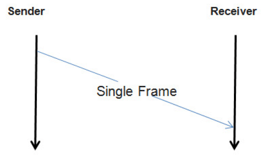
Transmission of an unsegmented Diagnostic Message on CAN bus.
A sender transmits a Single Frame (CAN Packet) that contains an entire Diagnostic Message.
Segmented message transmission
When a Diagnostic Message to be transmitted on CAN, contains payload which size is greater than a Single Frame capacity, then the message payload must be divided and transmitted by many CAN packets. The first packet to carry such messages is First Frame (CAN Packet) and its transmission is followed by Consecutive Frames (CAN Packets). A receiver controls the stream of incoming Consecutive Frames by sending Flow Control (CAN Packet) after First Frame and each complete transmission of Consecutive Frames block.
Note
The size of Consecutive Frames block is determined by Block Size parameter provided in Flow Control.
Note
The minimum time between two Consecutive Frames is determined by Separation Time Minimum parameter provided in Flow Control.
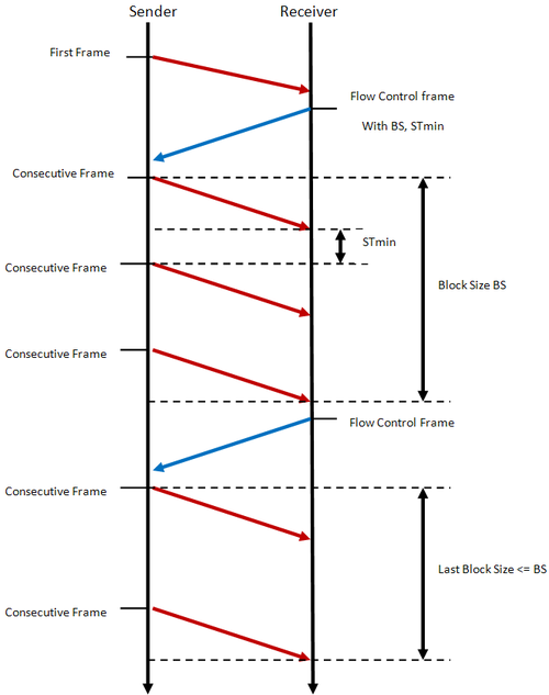
Transmission of a segmented Diagnostic Message on CAN bus.
A sender initiates Diagnostic Message transmission with a First Frame (CAN Packet) Then, a receiver controls the stream of incoming Consecutive Frames (CAN Packets) by transmitting Flow Controls (CAN Packets).
See also
Only the typical use case of Flow Control was described here. Check Flow Status parameter and meaning of its values to learn about other use cases.
Performance and Error Handling
ISO standards defines following time parameters Diagnostic on CAN communication:
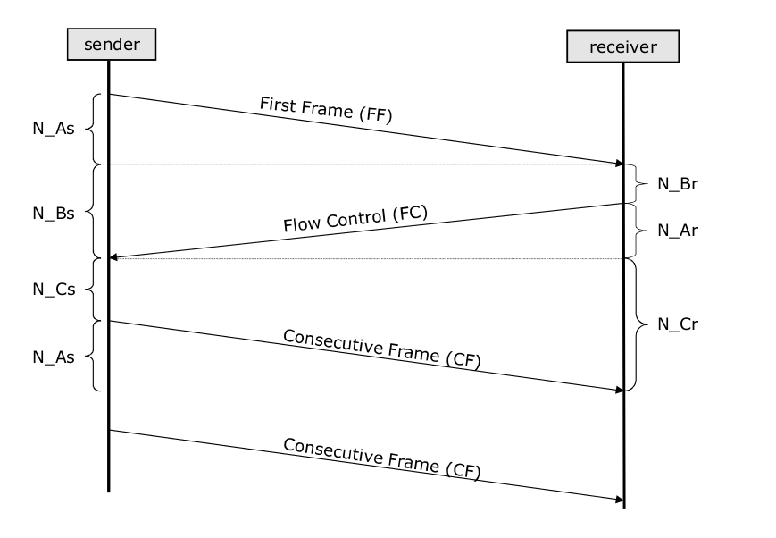
Network layer time values (N_As, N_Ar, N_Bs, N_Br, N_Cs, N_Cr) present during UDS on CAN communication.
Note
The example uses segmented diagnostic message transmission as it enables to present all CAN timing parameters. For unsegmented diagnostic message transmission though, the only applicable time parameter is N_As.
N_As
N_As is a time parameter related to transmission of any CAN Packet by a sender. It is measured from the beginning of the CAN Frame (that carries such CAN Packet) transmission till the reception of a confirmation that this CAN Frame was received by a receiver.
- Timeout value:
1000 ms
- Error handling:
If N_As timeout is exceeded, then the transmission of the diagnostic message shall be aborted.
- Affected CAN Packets:
N_Ar
N_Ar is a time parameter related to transmission of any CAN Packet by a receiver. It is measured from the beginning of the CAN Frame (that carries such CAN Packet) transmission till the reception of a confirmation that this CAN Frame was received by a sender.
- Timeout value:
1000 ms
- Error handling:
If N_Ar timeout is exceeded, then the reception of the diagnostic message shall be aborted.
- Affected CAN Packets:
N_Bs
N_Bs is a time parameter related to Flow Control (CAN Packet) reception by a sender. It is measured from the end of the last CAN Packet transmission (either transmitted First Frame, Consecutive Frame or received Flow Control), till the reception of Flow Control.
- Timeout value:
1000 ms
- Error handling:
If N_Bs timeout is exceeded, then the reception of the diagnostic message shall be aborted.
- Affected CAN Packets:
N_Br
N_Br is a time parameter related to Flow Control (CAN Packet) transmission by a receiver. It is measured from the end of the last CAN Packet transmission (either received First Frame, Consecutive Frame or transmitted Flow Control), till the start of Flow Control transmission.
- Performance requirement:
A receiving entity is obliged to transmit Flow Control packet before value of N_Br achieves maximal value threshold.
[N_Br] + [N_Ar] < 0.9 * [N_Bs timeout]
[N_Br max] = 900ms - [N_Ar]
- Affected CAN Packets:
N_Cs
N_Cs is a time parameter related to Consecutive Frame (CAN Packet) transmission by a sender. It is measured from the end of the last CAN Packet transmission (either received Flow Control or transmitted Consecutive Frame), till the start of Consecutive Frame transmission.
- Performance requirement:
A sending entity is obliged to transmit Consecutive Frame packet before value of N_Cs achieves maximal value threshold.
[N_Cs] + [N_As] < 0.9 * [N_Cr timeout]
[N_Cs max] = 900ms - [N_As]
- Affected CAN Packets:
N_Cr
N_Cr is a time parameter related to Consecutive Frame (CAN Packet) reception by a receiver. It is measured from the end of the last CAN Packet transmission (either transmitted Flow Control or received Consecutive Frame), till the reception of Consecutive Frame.
- Timeout value:
1000 ms
- Error handling:
If N_Cr timeout is exceeded, then the reception of the diagnostic message shall be aborted.
- Affected CAN Packets:
Unexpected Packet handling
- According to ISO 15765-2:2016:
As a general rule, arrival of an unexpected N_PDU from any node shall be ignored, with the exception of SF N_PDUs and physically addressed FF N_PDUs; functionally addressed FirstFrames shall be ignored. When the specified action is to ignore an unexpected N_PDU, this means that the network layer shall not notify the upper layers of its arrival.
Depending on the network layer design decision to support full- or half-duplex communication, the interpretation of “unexpected” differs: a) with half-duplex, point-to-point communication between two nodes is only possible in one direction at a time; b) with full-duplex, point-to-point communication between two nodes is possible in both directions at once.
Half-duplex
Half-duplex means that only one UDS message (in one direction) can be transmitted at a time. That means that each node has up to one role (either sender or receiver) at any time.
Handling of unexpected CAN packets in case of half-duplex communication:
Status |
Single Frame |
First Frame |
Consecutive Frame |
Flow Control |
Unknown |
|---|---|---|---|---|---|
Idle |
Process the Single Frame as the start of a new message. |
Process the First Frame as the start of a new message. |
Ignore |
Ignore |
Ignore |
Segmented message transmission in progress |
Ignore |
Ignore |
Ignore |
Ignore |
Ignore |
Segmented message reception in progress |
Terminate the current message reception and process the Single Frame as the start of a new message. |
Terminate the current message reception and process the First Frame as the start of a new message. |
If awaited, then process the Consecutive Frame in the on-going reception and perform required checks (e.g. Sequence Number in order). Otherwise, ignore it. |
Ignore |
Ignore |
Full-duplex
Full-duplex means that UDS messages can be transmitted in both directions at once. That means that a node could be sender of one UDS message and receiver of another one at the same time.
Handling of unexpected CAN packets in case of full-duplex communication:
Status |
Single Frame |
First Frame |
Consecutive Frame |
Flow Control |
Unknown |
|---|---|---|---|---|---|
Idle |
Process the Single Frame as the start of a new message. |
Process the First Frame as the start of a new message. |
Ignore |
Ignore |
Ignore |
Segmented message transmission in progress |
If a message reception is in progress then see the corresponding cell in the row below. Otherwise, process the Single Frame as the start of a new message. |
If a message reception is in progress then see the corresponding cell in the row below. Otherwise, process the First Frame as the start of a new message. |
If a message reception is in progress then see the corresponding cell in the row below. Otherwise, ignore it. |
Ignore |
Ignore |
Segmented message reception in progress |
Terminate the current message reception and process the Single Frame as the start of a new message. |
Terminate the current message reception and process the First Frame as the start of a new message. |
If awaited, then process the Consecutive Frame in the on-going reception and perform required checks (e.g. Sequence Number in order). Otherwise, ignore it. |
Ignore |
Ignore |